
Strength of nylon gears
A laser-sintered nylon 12 gear can fail at the tooth root, on the tooth flanks, in its web or at the shaft. The generator rates the teeth by ISO 6336, sizes the web so the teeth stay the weakest part of the gear, and the joint to the shaft is up to you. This page gives the numbers behind those ratings and the practical limits that matter when you design.
The material
Laser-sintered nylon 12 (PA 2200 powder) is a tough, semi-crystalline plastic. Parts are strongest in the plane they are printed in; our gears print flat, so the teeth and spokes are loaded in that plane.
| Property | Value | Source |
|---|---|---|
| Tensile modulus | 1650–1700 MPa | EOS data sheet; 1740–1790 MPa measured dry by Wingham et al. |
| Tensile strength, in plane / across layers | 48 / 42 MPa | EOS data sheet |
| Elongation at break, in plane / across layers | 18 % / 4 % | EOS data sheet; 25–30 % measured by Wingham et al. |
| Fatigue limit, fully reversed | 18 MPa at 20 °C | Sommer, Stockfleet and Hellmann, Polymers 2024 |
| Creep at 10 MPa for 100 h | 1.7 % at 23 °C, 2.5 % at 60 °C | Moeskops et al., SFF Symposium 2004 |
| Heat deflection temperature, 1.8 MPa | 64 °C | EOS data sheet |
| Steady-load service range | −40 to +80 °C | EOS product information |
The low elongation across layers is why we print gears flat, and why a part loaded through its layers (a tall hub pulled along its axis, for example) should be designed with extra margin.
How the teeth are rated
Ft = 2 T / d
The tangential force at the pitch circle follows from the torque T and the pitch diameter d. A 30 mm gear carrying 0.5 N·m has a tooth force of 33 N. Each tooth is a short cantilever, and ISO 6336-3 gives the root stress:
σF = Ft / (b · m) · YF · YS · Yε · Yβ · KA
YF and YS describe the tooth's shape and root fillet; the generator measures them on the actual generated tooth, so profile shift, undercut and backlash are included. Yε credits load sharing between teeth, Yβ credits helical teeth, and KA (1.25 by default) allows for shocks. Flank contact stress is checked by ISO 6336-2 for pairs, racks and rings. We checked the bending formula against finite-element models of 12 tooth forms, from 8 to 80 teeth and pressure angles of 14.5° to 25°: the formula is conservative by 5 to 14 % in every case.
Allowable stresses
At room temperature the generator allows 12 MPa in bending and 25 MPa in contact. A tooth is loaded one way only, so its fatigue strength is higher than the fully reversed limit of 18 MPa: about 23 to 26 MPa after a Goodman correction. 12 MPa is therefore about half the material's fatigue strength, before the service factor is applied to the load. No contact-fatigue data have been published for laser-sintered nylon 12, so the contact allowable is set conservatively.
Rated torque by size
Rated torque grows with module squared and roughly with tooth count. The table gives the continuous rated torque of a spur gear at the face width our catalog uses, at 20 °C, with KA = 1.25 and a mate of the same size. Use it to choose a pitch; the generator rates your exact design.
| Pitch | Face | 15 teeth | 20 teeth | 30 teeth | 50 teeth | 80 teeth |
|---|---|---|---|---|---|---|
| Module 0.5 | 3 mm | 0.013 | 0.023 | 0.037 | 0.067 | 0.11 |
| Module 1 | 6 mm | 0.10 | 0.18 | 0.30 | 0.54 | 0.89 |
| Module 1.5 | 10 mm | 0.38 | 0.68 | 1.1 | 2.0 | 3.3 |
| Module 2 | 12 mm | 0.80 | 1.4 | 2.4 | 4.3 | 7.1 |
| Module 3 | 18 mm | 2.7 | 4.9 | 8.1 | 14 | 24 |
| 32 DP | 3/16 in | 0.050 | 0.091 | 0.15 | 0.27 | 0.44 |
| 20 DP | 3/8 in | 0.26 | 0.46 | 0.77 | 1.4 | 2.3 |
| 12 DP | 5/8 in | 1.2 | 2.1 | 3.5 | 6.3 | 10 |
Rated torque in N·m at 20 °C, dry.
Small pinions are the weak link: below about 18 teeth the contact stress, not bending, sets the rating. Torque scales directly with face width, so doubling the face doubles the rating.
Temperature
Nylon 12 loses strength quickly as it warms, and a gear running dry at speed warms at the mesh. Sommer et al. measured the fatigue limit at 0, 20 and 40 °C; above 40 °C we scale it with the tensile-strength retention a powder-bed nylon 12 data sheet gives, so those rows are estimates.
| Running temperature | Tensile strength | Tensile modulus | Fatigue limit | Multiply the 20 °C torque rating by |
|---|---|---|---|---|
| 0 °C | 67 MPa | about 120 % | 26 MPa | 1.4 |
| 20 °C | 56 MPa | 100 % | 18 MPa | 1.0 |
| 40 °C | 47 MPa | about 60 % | 12 MPa | 0.67 |
| 60 °C (estimate) | about 37 MPa | about 40 % | about 10 MPa | 0.55 |
| 80 °C (estimate) | about 32 MPa | about 33 % | about 8.5 MPa | 0.47 |
To rate a warm gear, enter a lower allowable bending stress in the generator: 8 MPa at 40 °C, about 6.5 MPa at 60 °C. Keep sustained running below about 60 °C: the material softens sharply as it approaches its 64 °C heat-deflection temperature. Running against a metal gear, which carries heat away, and a light plastic-compatible grease both keep the teeth cooler. The VDI 2736 guideline gives a tooth-temperature estimate for dry-running plastic gears.
Moisture
Nylon 12 absorbs the least water of the common nylons, and in indoor air the effect on strength is small. A part soaked through is noticeably softer. Wingham et al. (Rapid Prototyping Journal, 2021) measured laser-sintered PA 2200:
| Condition | Water content | Tensile modulus | Tensile strength | Elongation at break |
|---|---|---|---|---|
| Dry, as printed | 0.05 % | about 1770 MPa | 49–50 MPa | 25–30 % |
| Partly wet | 0.54 % | 1408 MPa (−21 %) | 44.8 MPa (−8 %) | 36 % |
| Soaked (steam) | 0.84 % | 1066 MPa (−39 %) | 42.7 MPa (−13 %) | 46.5 % |
| Dried again | 0 % | 1638 MPa | 48.9 MPa | 24.5 % |
The change reverses when the part dries. For gears that run wet, take about 85 % of the rated torque and allow for softer, more flexible teeth. Nylon 12 also swells very little, so backlash barely changes with humidity.
Spoked gears
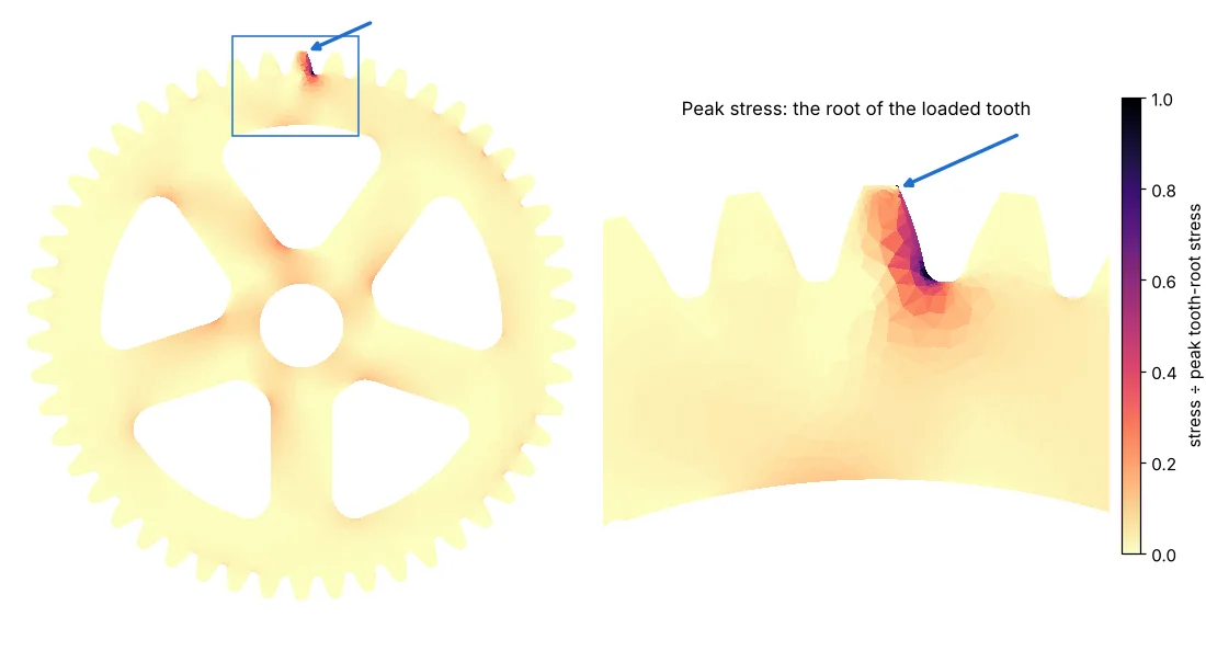
Spoke windows save weight and printing cost on larger gears, but the torque still has to travel from the teeth through the rim and spokes to the bore. We analysed spoked gears with finite elements across the full range the generator builds, from module 0.5 to 3, 30 to 140 teeth, 3 to 12 windows and small to large bores, loading a tooth both over a spoke and over a window. The generator sizes every web from the results: a rim under the teeth that thickens as the spokes get farther apart, a solid ring around the bore, spokes sized as beams for the module and number of windows, and generous fillets in the window corners. In every case analysed the web's peak stress is at most three quarters of the tooth-root stress, and typically a quarter, so the teeth remain the weakest part of the gear. The generator also chooses the number of spokes: of three to eight windows, it builds the set that uses the least material while meeting these rules, typically three on gears under about 40 teeth, four up to about 70 and five above. Small gears, where spokes would save little, stay solid.
Shaft connections
The teeth are only half the story. On coarser gears, from about module 1.25 or 24 diametral pitch upward, the joint to the shaft is usually weaker than the teeth, so choose it with the torque in mind:
| Connection | How it carries torque | Typical capacity | Advice |
|---|---|---|---|
| Plain round bore, press fit | Friction from the interference | Low, and it falls as the nylon relaxes over days | Use it to locate a gear on light-duty or hand-turned shafts, or add adhesive (methyl methacrylate bonds nylon best). |
| Set screw in a threaded insert | Screw point clamping the shaft | About 0.06 N·m (M2 on a small shaft) to 2.5 N·m (M5 on a 20 mm shaft) on a round shaft; a third of the tooth rating or less on module 2 and coarser | Grind a flat on the shaft under the screw. Use two screws at 90°, which roughly doubles the hold. Don't overtighten: the insert, not the screw, is the limit. |
| D-flat | Shape: the flat bears on the bore | Good when the flat is deep and the hub long | The usual choice for motor shafts. A deeper flat and a longer hub both raise capacity; double-D for reversing loads. |
| Keyway | Shape: the key bears on the nylon | Moderate; the bearing pressure on the key's side limits it | Keep the bearing pressure under about 20 MPa: torque ≈ 20 MPa × hub length × key height/2 × shaft radius. Lengthen the hub rather than widening the key. |
| Hex or square | Shape, over a large area | The highest of the bores | Best for printed gears that must carry their full rating. |
| Bolt circle to a metal hub | Bolts through the web | Highest; the metal hub carries the shaft | For torque beyond what the nylon round the bore can take. Use washers or a backing plate. |
A D-flat's capacity can be estimated from the bearing pressure on the flat: with pressure rising linearly from the middle of the flat, T ≈ p · b · (c/2)² / 3, where c is the chord length of the flat and b the engaged length. With p = 20 MPa, a 0.5 mm flat on an 8 mm shaft in a 6 mm-wide gear carries about 0.15 N·m, so give flats real depth and length when the torque is high. See hubs and bores and mounting nylon gears for fits and retention.
Designing with these numbers
- Start from the rated torque at your running temperature, and keep a safety factor of at least 1.5 for steady loads and 2 or more for shock.
- Check the shaft joint against the same torque; on coarse gears it usually limits first.
- Pair a printed gear with a metal or acetal mate where you can: it runs cooler and wears less than nylon on nylon.
- Test a prototype at your real load and temperature before ordering a batch.
Enter a torque and speed in the generator to see the rated torque and safety factors for your design. Open the generator.