
How Protogears parts are made
We print gears by selective laser sintering (SLS) in nylon 12, on an industrial EOS machine in Chicago. The same file that generates your drawings and downloads goes straight to the machine.
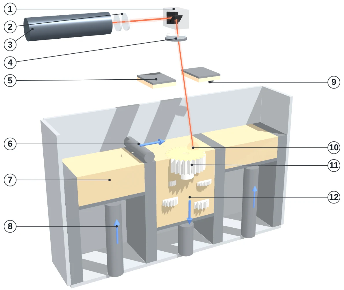
- X–Y scanning mirrors
- Beam-expanding lenses
- CO2 laser
- Focusing lens
- Heaters hold the powder just below melting
- Roller spreads a 0.1 mm layer
- Powder supply
- Supply piston rises
- Pyrometer reads the bed temperature
- Laser fuses the new layer
- Gear taking shape in the powder
- Build platform drops a layer
The process
- Your design becomes a build file. The STL is made by the same code that drew your gear in the generator, so the printed teeth are the teeth you saw.
- Parts are nested. Many orders share one build: parts are packed into the 200 × 250 × 330 mm build volume.
- The powder bed is heated to just below the melting point of the nylon.
- Layer by layer. A recoater spreads 0.1 mm of powder, and a CO2 laser traces the cross-section of every part, fusing the powder. The platform drops and the next layer is spread. Unfused powder supports the parts, so no support structures are needed and nothing scars the teeth.
- Cooling. The build cools slowly, for about as long as it took to print, so the parts do not warp.
- Unpacking and blasting. Parts are dug out of the powder cake and bead blasted clean.
- Inspection. We check gears by measurement over pins, the value printed on your data sheet.
- Packing. Each order ships with its data sheet.
What the laser does to the powder
Nylon 12 powder is a fine flour of grains about 0.05 mm across. The heaters keep the whole bed just below the melting point, so the laser only has to add a little energy: where it passes, the grains melt at their surfaces and flow together. The fused nylon is nearly solid, with a slightly grainy surface that gives SLS parts their matte finish.
Accuracy to expect
Laser-sintered parts are less precise than machined or molded ones. Print services commonly quote tolerances of about ±0.3 % of a dimension, with a floor of ±0.3 mm. For a gear, the error that matters is the tooth thickness, because it sets the backlash. That is why the generator recommends at least 0.05 mm of backlash per gear for printed pairs and adds an allowance to bores. Every gear we ship is measured over pins, and the result is checked against the value on its data sheet. We will publish our own measured tooth-thickness and runout figures from our calibration prints.
Orientation
We print gears lying flat, with the axis vertical. The tooth profile then lies in the plane of each layer, so it is traced in one smooth pass of the laser, and the bending load on each tooth runs along the layers, where the material is strongest.
The material: nylon 12 (EOS PA 2200)
| Property | Value |
|---|---|
| Tensile strength, in the layer plane | 48 MPa |
| Tensile strength, across layers | 42 MPa |
| Tensile modulus | 1650 MPa |
| Elongation at break, in the layer plane | 18 % |
| Melting temperature | 176 °C |
| Density | 0.93 g/cm³ |
Values from the EOS PA 2200 material data sheet. Properties depend on build position and process settings.
Nylon 12 is tough, dimensionally stable, resistant to oils, greases and most solvents, and absorbs much less water than other nylons. Its fine-grained surface needs no finishing on gear teeth.
Design rules for printed gears
The generator checks every design against these rules before you order. Rules marked required block the order; the others appear as printing notes.
| Rule | Limit | Why |
|---|---|---|
| Wall thickness, anywhere | 0.8 mm, required; 1.5 mm recommended | Thinner walls break during depowdering and blasting |
| Material under the teeth | 1.5 mm, required | The rim carries the tooth load |
| Hole diameter | 1.5 mm, required | Smaller holes fill with fused powder |
| Tooth space near the root | 0.3 mm, required; 0.5 mm recommended | Narrow spaces fill with partly fused powder |
| Module | 0.5 to 5 mm (5 to 48 DP) | Finer teeth are smaller than the process can resolve |
| Tip land | 0.3 mm recommended | Narrower tips print rounded |
| Solid sections | Under 10 mm in at least one direction | Thick solid sections shrink unevenly as they cool; spoke windows help |
| Large thin parts | Thickness at least 1/20 of the diameter | Thin discs and long thin racks can warp |
| Backlash | 0.05 to 0.1 mm per gear at module 1 | Allows for tolerance and moisture swelling |
| Bore allowance | +0.1 to +0.2 mm for a sliding fit | Laser-sintered holes come out slightly small |
The general limits follow published SLS design guides; the gear-specific values will be refined from our calibration prints.
Accuracy
We are measuring the accuracy of our process with a calibration set of gears from module 0.5 to 2, and will publish the results here, together with the bore allowances that give a sliding fit. The finest teeth we accept for printing are module 0.5 (about 48 DP).